Flyback Converter Design In Pspice
In this paper, we present, Basic flyback converter operation in part-II, Proposed flyback converter operation, Step By Step Design Procedure. Result & Discussion, in part-III, IV & V respectively. FLYBACK CONVERTER Converters can be classified as isolated and non-isolated. Flyback converter is one of the simple topology in isolated converters. Design calculations of Flyback converter presented in this project. Design is also simulated in PSPICE simulator with a switching frequency of 150KHz.
Ing. Cristoforo Baldoni
In this article we ‘ll see how to find the output power stage transfer function H(s), called the Control-to-Output function, of the most switching power supplies: BUCK, BOOST, BUCK-BOOST, HALF-BRIDGE, FULL BRIDGE, both in voltage mode control and current mode control. In spite of the complexity of the different types of power supplies that use one or more output feedback, the output power transfer function H(s), can be reduced to a few schematic categories of general validity. We’ ll see when it’s the case to consider the effects of the RHPZ, the Right Half Plane Zero, and what it means in practical terms.
Once the components for the specific power supply have been sized, we can estimate with good approximation the transfer function which describes mathematically the output power stage. As seen in the article about the determination of POLES and ZEROS by inspection, we ‘ll identify immediately the POLES and ZEROS which characterize the different switching categories.
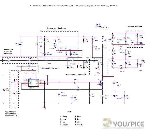
We ‘ll draw the Bode plots of these functions with PSpice, and, according to their characteristics, we ‘ll choose the most suitable compensator G(s), implementing the compensation network with the operational amplifiers embedded in the microcontrollers. The SPICE simulation of the open loop transfer function G(s)*H(s), will allows us to evaluate the results for the system stability. Finally, we ‘ll apply this method in two real switching power supply: a low power flyback converter and an off-line, half-bridge switching.
This method allows us to speed up the design of the compensator G(s) in the prototyping phase before the physical measurement with the instrumentation.
It’s strongly recommended the reading of these articles:
Accessing this article you can download the following SPICE simulation files about switching power supply compensation design:
-Forward function example
-Flyback function example
-Flyback function example with a Right Half Plane ZERO
-Origin POLE compensator
-Origin POLE Transfer function implementation
-Forward function compensated example
How often can you take driver improvement course in va. Acceptance by the CourtYour court may or may not accept the certificate of completion.
-One ZERO two POLES compensator
-One ZERO two POLES Transfer Function Implementation
-Flyback with RHPZ compensated
-Three POLES two ZEROS compensator
-Three POLES two ZEROS Transfer Function
-Transfer function of a real Flyback converter Outlook 2016 for mac cannot add imap account free.
-Compensator for the flyback converter
-Overall compensated transfer function of the flyback converter
-Transfer function of a real Forward converter
-Compensator for the Forward converter
-Transfer function of compensator for the Forward converter
-Overall compensated transfer function of the Forward converter
Premium Content
Login to buy access to this content
Analog Design and Simulation using OrCAD Capture and PSpice provides step-by-step instructions on how to use the Cadence/OrCAD family of Electronic Design Automation software for analog design and simulation. Organized into 22 chapters, each with exercises at the end, it explains how to start Capture and set up the project type and libraries for PSpice simulation. It also covers the use of AC analysis to calculate the frequency and phase response of a circuit and DC analysis to calculate the circuits bias point over a range of values.
The book describes a parametric sweep, which involves sweeping a parameter through a range of values, along with the use of Stimulus Editor to define transient analog and digital sources. It also examines the failure of simulations due to circuit errors and missing or incorrect parameters, and discusses the use of Monte Carlo analysis to estimate the response of a circuit when device model parameters are randomly varied between specified tolerance limits according to a specified statistical distribution. Other chapters focus on the use of worst-case analysis to identify the most critical components that will affect circuit performance, how to add and create PSpice models, and how the frequency-related signal and dispersion losses of transmission lines affect the signal integrity of high-speed signals via the transmission lines.
Practitioners, researchers, and those interested in using the Cadence/OrCAD professional simulation software to design and analyze electronic circuits will find the information, methods, compounds, and experiments described in this book extremely useful.